
AS-Interface Contact Units (Slaves)
Instead of up to 10 cable lines per slave, ASi requires only two wires which are connected by insulation piercing (IDC technology) and looped through to all the assigned slaves. Up to 62 control units can be connected to one 2-conductor cable. This saves work, cuts installation times, reduces the number of potential errors and, in case of need, can easily be changed or extended. Due to the flexible AS-Interface network structure, the Schlegel slaves can be connected to any position. Each control and signalling unit means a separate node with individual address in the AS-Interface system.
Slave Characteristics
- Certified AS-Interface slave with two input functions and one dimmable output to accept a pluggable LED with T5,5K socket
- Same size as on the standard contact blocks of the "A...“ type series
- Failure-safe operation even under extreme environmental conditions (e.g. welding plants, frequency converters)
- AS-Interface profile S-B.A.E (extended address mode)
- Up to max. 62 slaves can be connected to one single AS-Interface cable
- Input data portsD2 and D3
- Output data ports D0 and D1
- The LED can be dimmed in 4 steps while toggling between two brightness levels is possible via the outputs D0 and D1.
- Output with short-circuit and overload protection
- Easy connection via 2-pole IDC connector
- 2- and 3-position selector and key switches are possible
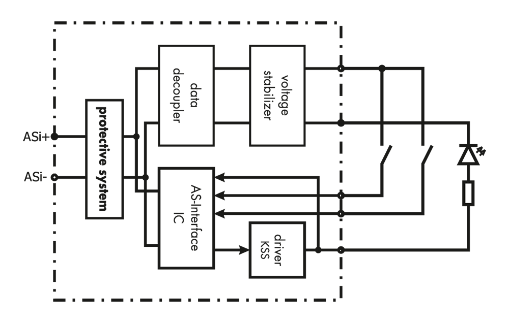
Block Diagram
Data Bits of the Outputs and Inputs
General
| Outputs | ||
| data bit | info (Interface 3) | state |
| D0 | 0 | LED off |
| 1 | LED on | |
|
D1 |
0 | LED off |
| 1 | LED on | |
| Inputs | ||
| data bit | info (Interface 3) | state |
| D2 | 0 | switch 1 not activated |
| 1 | switch 1 activated | |
|
D3 |
0 | switch 2 not activated |
| 1 | switch 2 activated | |
Pushbuttons
| pushbuttons | ||
| switching position | not activated | activated |
| data bit | ||
| D13 | 0 | 1 |
| D12 | 0 | 1 |
2-position selector/key switches (1 plunger)
| 2 positions, 1 plunger | 0 - 1 | |
| switching position | 0 | 1 |
| data bit | ||
| D13 | 0 | 1 |
| D12 | 0 | 1 |
3-position selector/key switches (2 plungers)
| 3 positions, 2 plungers | 1 - 0 - 2 | ||
| switching positions | 1 | 0 | 2 |
| data bit | |||
| D13 | 1 | 0 | 0 |
| D12 | 0 | 0 | 1 |
Note
for the use of 2-position selector and key switches: As actuator and ASI slave can be snapped together turned by 90°, the following basic positions must be observed for a clear assignment of the input bits (DI2, DI3) :
- ASI slave connections upward
- locating lug upward
AS-Interface parameters for pulse-width modulation of the LED
P2 P1 P0
1 1 1 output D0 continuous wave (default)
1 0 1 output D0 50% (PWM frequency 125 Hz)
1 1 0 output D0 25% (PWM frequency 125 Hz)
1 0 0 output D0 12.5 % (PWM frequency 125 Hz)
0 1 1 output D1 continuous wave (default)
0 0 1 output D1 50% (PWM frequency 125 Hz)
0 1 0 output D1 25% (PWM frequency 125 Hz)
0 0 0 output D1 12.5% (PWM frequency 125 Hz)
LED Brightness Control
For the brightness control of the LED (4-step dimming) the pulse-duty factor of the pulse-width modulated voltage (PWM) can be adjusted by a parameter request of the master. The output current is thereby reduced in four steps (individually for each output D0/D1), namely from 100% to 50%, 25% or 12.5% of the continuous current. Due to the individual LED control via the outputs D0 or D1, it is possible to toggle between two different brightness levels. This is achieved via the „Write Parameter Call“.
AS-Interface Parameters for pulse-width modulation of the LED
| P2 | P1 | P0 | |
| 1 | 1 | 1 | output D0 continuous wave (default) |
| 1 | 0 | 1 | output D0 50% (PWM frequency 125 Hz) |
| 1 | 1 | 0 | output D0 25% (PWM frequency 125 Hz) |
| 1 | 0 | 0 | output D0 12,5 % (PWM frequency 125 Hz) |
| 0 | 1 | 1 | output D1 continuous wave (default) |
| 0 | 0 | 1 | output D1 50% (PWM frequency 125 Hz) |
| 0 | 1 | 0 | output D1 25% (PWM frequency 125 Hz) |
| 0 | 0 | 0 | output D1 12.5% (PWM frequency 125 Hz) |
| 0 | 0 | A4 | A3 | A2 | A1 | A0 | 1 | Sel | P2 | P1 | P0 | PB | 1 |
Norms and Standards
AS-Interface, the standard of the lower field level, complies with the European norm EN 50295 and the worl standard IEC 62026-2.
Certification and AS-Interface Logo
The reliable function and failure immunity of the Schlegel slaves were tested by an authorised laboratory. All certified products are bearing the AS-Interface Certification Logo.
- AS-Interface specification, version 2.11, revision 1
- CE
- UL
- CSA
Connection of Slaves
The slaves are connected (by insulation piercing) to the flexible equipment wire via a 2-pole, reverse polarity protected connector (3.96mm) with lock mechanism and strain relief (refer to the
accessories).

Cable Requirements
The connection cable must meet the following requirements:
- Colour coding: brown: ASI+ / blue: ASI-
- Insulation: medium hard PVC insulation, suitable for insulation piercing (IDC technology)
- Single conductor size: AWG 18 (0.8...1.0 mm²)
- Outer Ø: min 1.0, max. 2.28mm
- Operating temperature: -30°C <= T <= 90°C
- Approvals: VDE 0881 / MIL-W-1687 8D / UL 1007 or 1061 or 1095
Recommended connection cable: Flexible equipment wire “ASI_SL2AWG18”
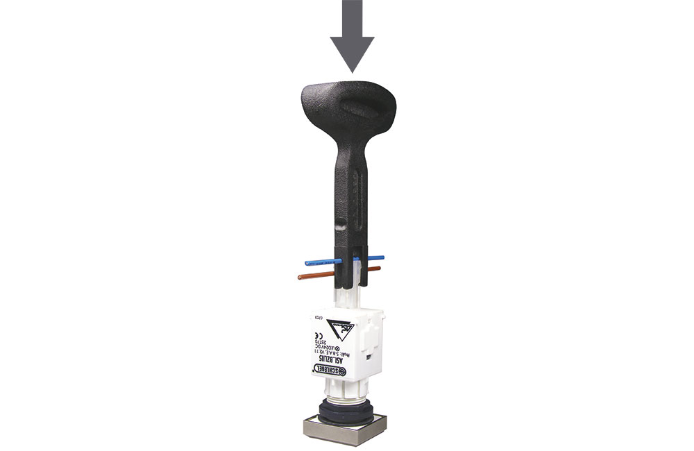
Connection Using a Press-fit Tool
The tool “ASI_ MRT” serves to press the single conductors into the IDC connector. Recommendation: By using the cover “ASI_K2” an optimal strain relief is achieved at the IDC connector!
Attention: Take care of using the correct conductor colour/polarity before pressing in!
Brown: ASI+
Blue: ASI-
Connection to AS-Interface Profile Line
Depending on the case of application, there are different possibilities to connect a double-core flexible wire (AWG18) to the AS-Interface profile line (refer to the accessories).
Addressing of the Slaves
Each AS-Interface slave gets an individual address allowing the master to identify it. Possible addresses are from1A to 31A and 1B to 31B (A/B slaves, version 2.1). The address 0 has a special
function. Depending on the technology that is used, addressing of the slaves is done either before or after the assembly.
Addressing Possibilities
1. Addressing cable + addressing device
The easiest way to assign the addresses is to use a hand-held addressing device which is directly connected to the slave via the Schlegel addressing cable „ASI_PK500M12“. The arrangement of the devices at the AS-Interface cable is independent from the
assignment of the addresses.
2. Addressing with AS-Interface Controller / PLC
Various producers of controllers/PLC support the following addressing possibilities:
- automatic addressing of the complete system
- individual addressing via the connected master
- individual addressing via PC, software-implemented
Note:
- avoid double addressing!
- A/B slaves (V2.1) cannot utilise the 4th output data bit because it is used to change over to the B slaves.
- A/B slaves can be operated with AS-Interface 2.0 masters, provided the following is strictly observed:
-> only „A“ addresses are used
-> the 4th data bit must permanently be „0“
-> the 4th parameter bit must be „1“